As I mentioned on a previous post, it was quite of a challenge working with the Teltronic M4000 because there is no information available anywhere. A friend of mine lend me one to see if I can program the Teltronic M4000 on the amateur radio bands but I got no programming cable or programming software with the radio.
I started the research and found at some forums that the programming cable of the Teltronic M4000 is the same as the MDT-400. That information alongside the “pinout” of the microphone it helped me to identify the pinout of the Teltronic M4000 programming cable.
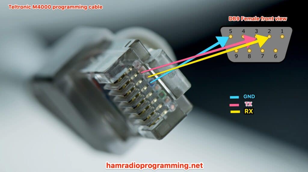
Based on my research, the programming cable pinout is as follows:
| DB9 | RJ45 |
|---|---|
| PIN 2 | PIN 3 |
| PIN 3 | PIN 2 |
| PIN 5 | PIN 4 |
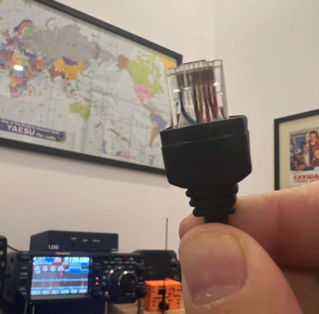
If you see the following image of the microphone connector you will see that pin 2 and pin 3 are not in use and the previously shown pinout makes sense.

Because I own a few Serial-to-USB adapters I decided to move forward and try to build the programming cable using a DB9 connector instead of going directly to a USB-to-TTL to the radio. I will try this in the future but if you think about it it makes no sense if you own the serial-to-usb adapters.
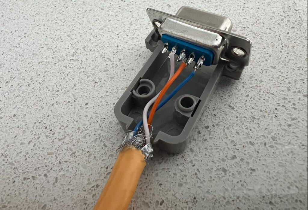
Grabbed a broken network patch cord, kept the RJ45 that was in good shape and cut the other end to solder the DB9 connector. Solder the 3 wires needed to create the programming cable.

I know, I suck at soldering
This is a graphical representation of the pinout

I tested the programming cable and it worked perfeclty fine on all the Teltronic M4000 radios I tested it on.
Hope this post helped you understand how to build your own programming cable. If you have any questions feel free to leave a comment here or publish a post on the Teltronic Radios user forum.

[…] Build the Teltronic M4000 programming cable using a computer network patchcord […]