As I mentioned in previous posts, I consider the Vertex VX-2200 and the Vertex VX-2100 as great radios for doing APRS and packet radio. But why I like this radios for this kind of amateur radio activities? It’s because the radio includes an accessory connector in the back from which you can actually manage the hole radio.
Unlike other radios where you need to use at least 2 different connectors, one for the audio output (mono plug) and one for the PTT activation and the audio input (microphone connector) these Vertex radios allows you to do packet radio and APRS using just one connector. In my opinion, less cables is better.
The connector I’m describing here is a 15 pin DSUB connector.
Vertex VX-2200 and VX-2100 accessory connector pinout
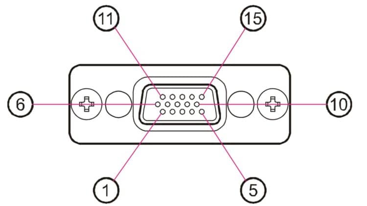
Pin 1: AF IN (ANALOG INPUT)
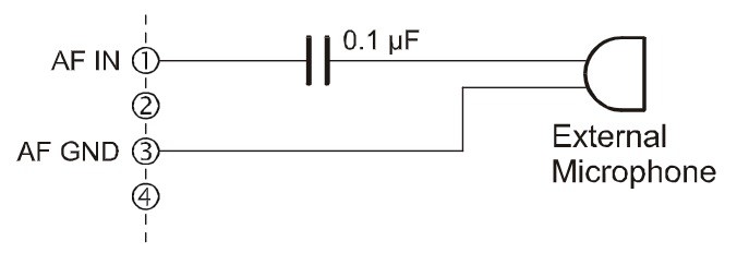
External Microphone Input. Nominal input level is 6mV at 600-ohm. When connect the External Microphone to this port, insert a 0.1 µF coupling capacitor between the micro-phone and this port; as shown illustration.
Pin 2: AF OUT (ANALOG OUTPUT)
Low-level receiver output. Peak signal level is 150 mV at 600-ohm.
Pin 3: AF GND
Ground for all logic levels and power supply return.
Pin 4: DC OUT (13.6 V DC OUTPUT)
Switched 13.6V output for supplying power to an accessory.
Pin 5: RSSI (ANALOG OUTPUT)
A DC voltage proportional to the strength of the signal currently being received (Receiver Signal Strength Indicator) is provided on this pin. This low impedance output is gererated by the receiver IF sub-system and bufferd by an internal op-amp. Typical output voltages are 1 V (@No Signal Input) through 2.0 V (@50 dB Signal Input).
Pin 6: EXT PTT
Shorting this port to ground causes the transceiver to be placed in the Transmit mode, while opening the connection to this port returns the transceiver to the
Receive mode. Opening voltage is 5 V, closed current approx. 5 mA.
Pin 7: TRX
This port is intended for controlling an external TX/RX switching circuit. This port is open collector output which can sink approx. 100 mA when active. Max. voltage is 16V.
Pin 8: IGN (IGNITION SENSE FEATURE)
The VX-2100/-2200 may be automatically be switched to the STND-BY mode when the vehicle’s ignition key is turned on. Maximum current is 20 mA.
Pin 9 – 12: ACC1 – ACC4 (ACCESSORY PORT)
These port features can be programmed via the CE82 programmer. Each port is open collector output which can sink approx. 100 mA when active. Max. output 16V.
When the input is selected, it becomes active between 2V and 16V.
Pin 13: ACC5 (ACCESSORY PORT)
The port 5 is available to set only for Output function, and active logic is the opposite side against the Port 1 Max.output 5V, closed current approx. 1 mA.
(CMOS output)
Pin 14: ACC6 (ACCESSORY PORT)
The port 6 is available to set only for Input function, and active logic is the opposite side against the Port 1 Max.input 5V. (CMOS input)
Pin 15: GND
Chassis ground
Vertex VX-2200 and VX-2100 accessory connector – programmable pins
Using the programming instructions of the vertex vx-2200 and the programming instructions of the vertex vx-2100 you can configure pin 9 through 12 for your specific needs.
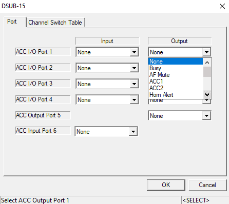
Using the CE-82 software you can configure the behaviour of the programmable pins. The following is a capture of some of the available options you have.
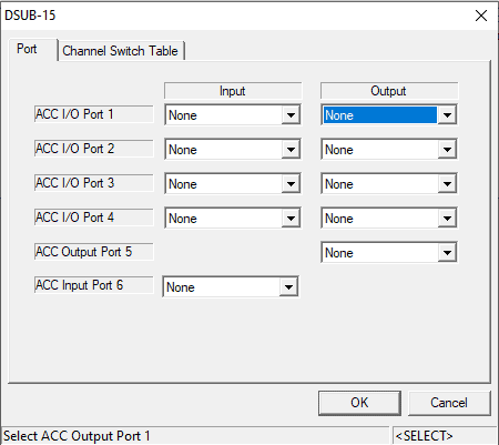
To access this, you need to click the common menu and then Sub15 port. The following are some of the available options of the input pins.
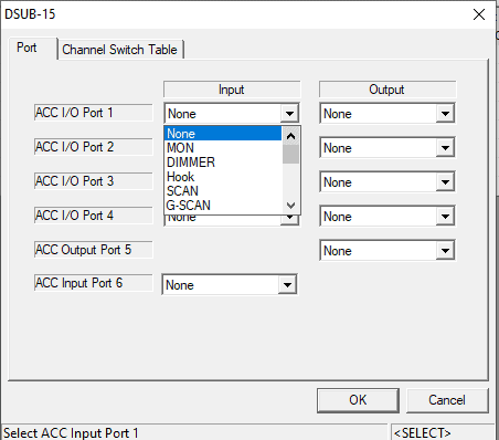
The following are some of the available options of the output pins.
Hope this post helped you understand the accesory port pinout of the accesory port of the VX2200 and VX2100 vertex radios. If you have any questions please leave a comment below, this will help new visitors in the future. Also, you can post your question on the Vertex radio user forum.

Thank you for taking the time to share your information, it was very helpful.
Glad it helped. I will publish a new blog post about doing APRS with this radio
73 de LU9CNS
thank you .i want the cable schematic to make it for me